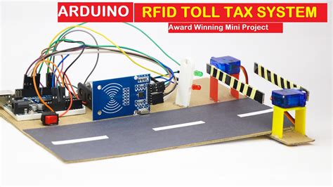
circuit diagram of rfid based toll collection system As an educational project, we are going to make a basic system where each vehicle will have a preregistered unique ID (using an RFID card). When the driver arrives at the toll plaza, the driver punches the ID to a specific .
Find many great new & used options and get the best deals for Nintendo 3DS .
0 · rfid toll gate
1 · rfid toll collection system
2 · automatic toll gate system
3 · arduino toll gate
NFC stands for Near Field Communications, a short-range wireless technology operating at 13.56 MHz that enables communication between devices at a distance less than 10 cm and a transmission rate of up to 424 .
rfid toll gate
Automated toll collection system using RFID introduces the Automatic Smart Toll Tax Collection System, employing an RFID Module and Arduino. With the increasing congestion at toll .In this paper, we present the design and implementation of an RFID-based toll collection system using Arduino microcontroller boards. The proposed system leverages Radio-Frequency .

what is a semi passive rfid tags quizlet
Circuit Diagram for Toll collection system using RFID. Here is the circuit diagram which makes this project. I have given a step-by-step explanation of how to make connections . Hey Friends In This Video I Will Show You How To Make RFID Based Automated Toll Collection System Using ArduinoCode And Circuit Diagram:- https://github.com/.Design and implement an Arduino based Toll tax collection system utilizing RFID technology for payment and Infrared Sensor for vehicle detection.
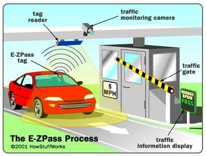
As an educational project, we are going to make a basic system where each vehicle will have a preregistered unique ID (using an RFID card). When the driver arrives at the toll plaza, the driver punches the ID to a specific . The document discusses an electronic toll collection system that uses radio frequency identification (RFID) technology. It describes the key components of RFID tags and readers that allow the system to automatically .
Here is the Rfid based arduino toll system diagram to make the circuit. The circuit is easy to make and there is no need of any breadboard here. Further to make it easier I will . Circuit diagram for Arduino RFID Barrier System With OLED Display. This is the circuit that we will use in this project, below I will explain the connections components wise. Circuit to connect Arduino uno and RFID . The circuit for RFID Based Toll Tax Collection System is given below. The circuit is based on the above flowchart with the use of necessary electronic components. The RFID .
Automated toll collection system using RFID introduces the Automatic Smart Toll Tax Collection System, employing an RFID Module and Arduino. With the increasing congestion at toll .In this paper, we present the design and implementation of an RFID-based toll collection system using Arduino microcontroller boards. The proposed system leverages Radio-Frequency . Circuit Diagram for Toll collection system using RFID. Here is the circuit diagram which makes this project. I have given a step-by-step explanation of how to make connections . Hey Friends In This Video I Will Show You How To Make RFID Based Automated Toll Collection System Using ArduinoCode And Circuit Diagram:- https://github.com/.
Design and implement an Arduino based Toll tax collection system utilizing RFID technology for payment and Infrared Sensor for vehicle detection. As an educational project, we are going to make a basic system where each vehicle will have a preregistered unique ID (using an RFID card). When the driver arrives at . The document discusses an electronic toll collection system that uses radio frequency identification (RFID) technology. It describes the key components of RFID tags and . Here is the Rfid based arduino toll system diagram to make the circuit. The circuit is easy to make and there is no need of any breadboard here. Further to make it easier I will .
Circuit diagram for Arduino RFID Barrier System With OLED Display. This is the circuit that we will use in this project, below I will explain the connections components wise. . The circuit for RFID Based Toll Tax Collection System is given below. The circuit is based on the above flowchart with the use of necessary electronic components. The RFID .Automated toll collection system using RFID introduces the Automatic Smart Toll Tax Collection System, employing an RFID Module and Arduino. With the increasing congestion at toll .
In this paper, we present the design and implementation of an RFID-based toll collection system using Arduino microcontroller boards. The proposed system leverages Radio-Frequency . Circuit Diagram for Toll collection system using RFID. Here is the circuit diagram which makes this project. I have given a step-by-step explanation of how to make connections . Hey Friends In This Video I Will Show You How To Make RFID Based Automated Toll Collection System Using ArduinoCode And Circuit Diagram:- https://github.com/.Design and implement an Arduino based Toll tax collection system utilizing RFID technology for payment and Infrared Sensor for vehicle detection.
As an educational project, we are going to make a basic system where each vehicle will have a preregistered unique ID (using an RFID card). When the driver arrives at . The document discusses an electronic toll collection system that uses radio frequency identification (RFID) technology. It describes the key components of RFID tags and . Here is the Rfid based arduino toll system diagram to make the circuit. The circuit is easy to make and there is no need of any breadboard here. Further to make it easier I will .
rfid toll collection system
automatic toll gate system
wet inlay rfid tags
arduino toll gate

512 GB. 4800 mAh. Check price. List of best smartphones with NFC. Latest cell phones with NFC. Find out which mobile phone has NFC feature. Phones from all brands: Samsung, apple, xiaomi, huawei and more. Which android or iphone .Function nfc.write writes an NdefMessage to a NFC tag.. On Android this method must be called from within an NDEF Event Handler.. On iOS this method can be called outside the NDEF Event Handler, it will start a new scanning session. .
circuit diagram of rfid based toll collection system|rfid toll gate